LArSoft
Software for Liquid Argon time projection chambers
LArSoft V10+ geometry system overview for users and detector geometry developers.
Goal of this page
This page is for people who need to use or write their own detector geometry. Section 1 describes the overall structure of the geometry system. An overview of the specific classes, identifiers, navigation and iteration tools follows in Sect. 2. (Please refer to the classes themselves for details of the information available from each class.) Sect. 3 then describes the features that allow customization of the geometry for specific LArTPC-based experiments.
Background on geometry
The background on the geometry for LArSoft v10+ can be found at: LArSoft.org/LArSoft Geometry V10+
1. High-level structure of the LArSoft geometry
The existing geometry model is supported by three sub-systems, each with a separate art service / LArSoft service provider:
- The core geometry (
geo::GeometryCore), which manages the physical volumes, - An experiment-customizable readout geometry that uses the core geometry to associate readout concepts (such as “channels”) to geometry objects (such as “wires” or “pixels”). The readout geometry:
- is customizable by each experiment (“standard” wire-based readout available)
- chooses the procedures to sort readout elements (e.g.
geo::WireReadoutSorter) - chooses the implementation of the wire or pixel readout (e.g.
geo::WireReadoutGeom) - maps logical readout channels to and from wires or pixels
- Provides access to view and signal type of planes for wire readouts
- Provides the “coordinate” of a point corresponding to the nearest wire or pixel
- An auxiliary geometry (
geo::AuxDetGeometryCore) that supports geometry elements outside of the cryostats.
For jobs that run in art, a geometry configuration writer service can be enabled that will store the current geometry configuration in run records, so that subsequent jobs can check that the geometry used is the same.
These sub-systems are described in more detail below.
Core Geometry
The class that describes the physical geometrical volumes is the geo::GeometryCore provider, which is normally accessed within a framework job through the geo::Geometry service. (For details on the structure of LArSoft services and providers, see Here.) The geo::GeometryCore is not experiment-customizable but is intended to represent the physical volumes common to all LAr TPC detectors supported by LArSoft. It is responsible for:
- managing the ROOT geometry description and its GDML source
- providing access to the LArSoft description of physical-volume detector components
- facilitating volume-geometry iteration on detector components by type
- maintaining relations between components
As of LArSoft v10, the physical volumes accessible through geo::GeometryCore include the cryostats and all TPCs and optical detectors within each cryostat (geo::CryostatGeo, geo::TPCGeo, and geo::OpDetGeo, respectively).
To load the geometry in an art framework job, the following should be part of the configuration:
services.Geometry: {
  SortingParameters: { tool_type: MyGeoObjectSorter ... }
  ...
}
Optical geometry
LArSoft assumes that optical detectors are directly contained by cryostats. Consequently all optical-geometry information is provided through the geo::GeometryCore provider.
Readout geometry
Whereas all TPCs contain cathodes and anodes, the manner in which signals are read from the anodes varies. Because of this variation in readout approaches, as of LArSoft v10, the readout geometry is separated from and layered on top of the main geometry system. This allows the readout geometry to still be aware of universal LArTPC geometry concepts while supporting the specific readout approach.
LArSoft supports the abstract geo::WireReadoutGeom provider, which is enabled in the art framework as the geo::WireReadout service. Experiments inherit from the geo::WireReadoutGeom provider to express wire-readout behavior specific to their detector(s). Like the main geometry system, readout elements may be iterated through using the interface discussed below in element iteration.
To use the readout geometry in an art job, users should include the following in their job configuration:
services.WireReadout: {
  service_provider: ExperimentSpecificWireReadout
  SortingParameters: { tool_type: MyWireReadoutSorter ... }
  ...
}
LArSoft will soon support the geo::PixelReadoutGeom provider for pixel readouts.
Auxiliary geometry
As mentioned HERE, LArSoft supports an auxiliary geometry system (represented by the geo::AuxDetGeometryCore class) that contains elements not part of the LArTPC cryostats. When constructing the auxiliary geometry, any elements labeled “volAuxDet” within the GDML file will be represented as geo::AuxDetGeo objects and owned by the geo::AuxDetGeometryCore instance. Each of the geo::AuxDetGeo objects in turn contain geo::AuxDetSensitiveGeo objects, which correspond to volumes within the GDML that are marked sensitive for Geant4’s use. How these volumes are used is experiment-specific, and users should refer to their experiment’s guidance.
As of LArSoft v10, the auxiliary geometry is not automatically loaded with the rest of the main geometry system. To load it in an art framework job, the following should be part of the job configuration:
services.AuxDetGeometry: {
  SortingParameters: { tool_type: MyAuxDetSorter ... }
  ReadoutInitializer: { tool_type: MyAuxDetInitializer ... }
  ...
}
Initialization of the auxiliary geometry system is a specialized topic and discussed more fully below in Writing your own auxiliary geometry initializer.
Geometry configuration writer
In the context of multi-stage workflow, it is necessary to use the same geometry for each stage. To help ensure this, there is a dedicated art framework service called GeometryConfigurationWriter, which inserts basic metadata about the geometry into each art::Run object. When encountering a new run, the metadata of the current geometry is checked against any stored metadata from a previous stage. If an incompatibility is detected, an exception will be thrown by the service, ending the framework job. To enable this service as part of a framework job, a user should include the following as part of a job configuration:
services.GeometryConfigurationWriter: {}
2. Core Geometry elements
LArSoft supports the geo::CryostatGeo, geo::TPCGeo, and geo::OpDetGeo classes (representing physical geometry characteristics), and the geo::PlaneGeo and geo::WireGeo classes (representing readout elements). (Additional elements will become available when pixel readouts are fully implemented.) Although the exact interface depends on the class, each class provides position and physical-extent information as well as an identifier to disambiguate one instance from another. In addition, the geometry system provides a reverse lookup mapping so that, given a particular point in 3D space, the corresponding (or closest) geometry element can be inspected.
Note that the wire readout element geo::WireGeo represents a single physical wire placement in a single TPC. Cases where multiple physical wires are connected to the same logical readout channel are handled in the mapping between wires and logical readout channels. Cases where one physical wire is split between two logical readout channels also occur. These are currently handled by creating two logical wires, one for each logical readout channel.
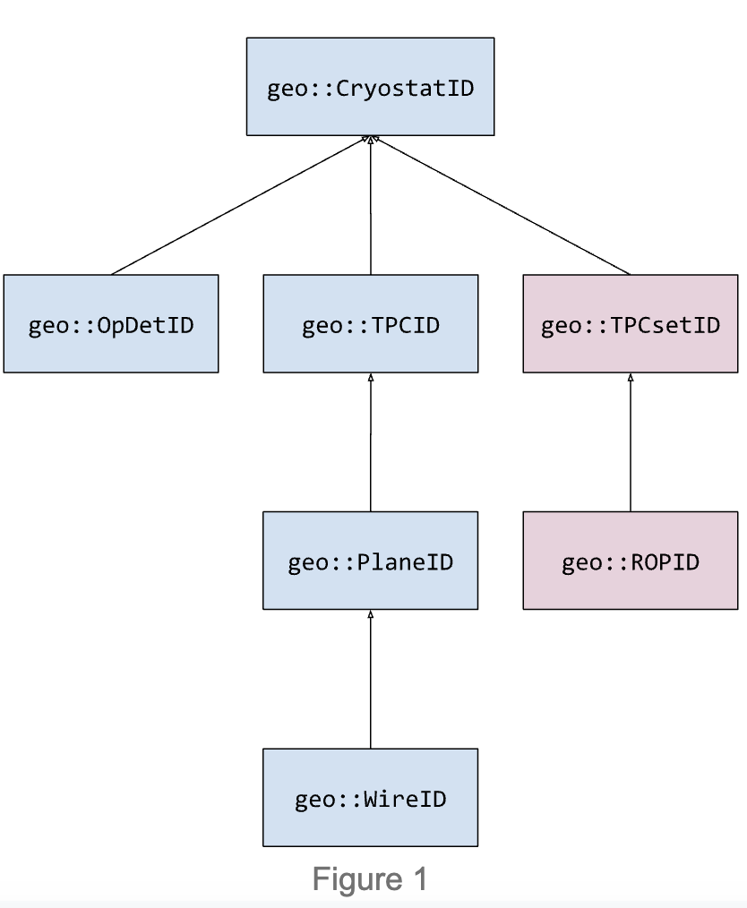
Element identifiers
Each geometry element is identified by a unique combination of numbers according to its inclusion in the geometrical hierarchy. The identifier of an element is a C++ class that inherits from the identifier of its parent (if one exists). The hierarchy is shown below.
With this pattern, any interface expecting a certain ID type can also accept arguments of derived types. For example:
// Get TPC 2 from cryostat 1
geo::TPCGeo const& tpc1 = geom->TPC(geo::TPCID{1, 2});

// Get TPC corresponding to wire 4 from plane 3 of TPC 2 from cryostat 1
geo::TPCGeo const& tpc2 = geom->TPC(geo::WireID{1, 2, 3, 4});

// They refer to the same TPC.
assert(tpc1 == tpc2);
All identifiers are zero-based and numbered compactly. For example:
- The first cryostat has an ID of
geo::CryostatID{0}. - The first TPC in the first cryostat has an ID of
geo::TPCID{0, 0}, where the first number is the index of the first cryostat, and the second number is the index of the first TPC within that cryostat. - For cryostat 0 with n TPCs, the TPC index values range from 0 to n - 1, resulting in
geo::TPCIDvalues of {0, 0} to {0, n-1}. - The pattern continues down the hierarchy, adding another number to the identifier depending on which level of the hierarchy the element resides.
The identifier system is not closed: a user may wish to inherit from one of the above identifier classes as a means of extending the hierarchy. However, the geometry system interface may not be able to intelligently make use of the new identifier depending on what is desired. In such cases, the user should contact LArSoft developers for guidance.
N.B. The auxiliary detector system is not included as part of the element identifier hierarchy.
Element iteration
An important feature of the geometry system is the ability to iterate through the geometry elements, as defined HERE. This is done by using the Iterate<T> interface provided by geo::GeometryCore and geo::WireReadoutGeom providers. For example, to iterate through wire IDs:
// Iterate through all wire IDs in the detector
for (auto const& wireID : wireReadoutGeom->Iterate<geo::WireID>()) {
  ...
}

// Iterate through all wire IDs in cryostat 1
for (auto const& wireID : wireReadoutGeom->Iterate<geo::WireID>(geo::CryostatID{1})) {
  ...
}
The iteration system is also designed to work seamlessly with geometry elements as well, so that if iteration over the elements themselves were desired, the ID suffix of “Iterate<ID>” can be replaced with “Iterate<Geo>”:
// Iterate through all wire objects in the detector
for (auto const& wireGeo : wireReadoutGeom->Iterate<geo::WireGeo>()) {
  ...
}

// Iterate through all wire objects in cryostat 1
for (auto const& wireGeo : wireReadoutGeom->Iterate<geo::WireGeo>(geo::CryostatID{1})) {
  ...
}
Iteration order and sorting
The order in which the above iteration occurs depends on the sorting algorithm specified by the user when constructing the geometry system. This specification happens when (a) explicitly constructing the geometry system in C++ code, or (b) constructing the geometry through a framework configuration file.
Sorting happens upon construction of the geometry system. After all geometry elements have been loaded into memory, the geometry tree is traversed downward from the top-most volume, sorting each set of elements as they are visited. For example, all cryostats are sorted first, then all TPCs contained by each cryostat are sorted, etc. LArSoft provides standard, default sorters for each of its geometry systems. Those interested in creating and enabling their own sorting algorithms should refer to the section below on writing your own geometry element sorter.
3. Customizing a geometry to fit in LArSoft
In this section we cover how to customize the LArSoft geometry facilities whenever the available ones are insufficient. Each of the three subsystems have element sorters that can be customized; the auxiliary geometry initialization step itself can be customized; and last, we discuss how to write and visualize your own GDML-based geometry.
Writing your own geometry element sorter
As of LArSoft v10, all elements of the physical, readout, and auxiliary geometry systems are sorted according to user-defined concrete sorter classes. Each sorter class contains virtual functions that, when overridden, provide the sorting behavior desired for a given level of the geometry hierarchy. Each sorting algorithm must model the Compare requirement as specified by the C++ standard template library and as used by the std::sort algorithm. The form of these sorters is shown below for the different geometry systems. Sibling volumes may not influence the sorting of a given volume’s subvolumes (e.g. sorting the TPCs of one cryostat should not be influenced by a different cryostat).
Physical geometry sorter (standard sorter available)
#include "larcorealg/Geometry/GeoObjectSorter.h"

class MyGeoObjectSorter : public geo::GeoObjectSorter {
public:
  explicit MyGeoObjectSorter(fhicl::ParameterSet const&);
private:
  bool compareCryostats(CryostatGeo const& c1, CryostatGeo const& c2) const override;
  bool compareTPCs(TPCGeo const& t1, TPCGeo const& t2) const override;
  bool compareOpDets(OpDetGeo const& od1, OpDetGeo const& od2) const override; // optional
};
Wire readout sorter (standard sorter available)
#include "larcorealg/Geometry/WireReadoutSorter.h"

class MyWireReadoutSorter : public geo::WireReadoutSorter {
public:
  explicit MyWireReadoutSorter(fhicl::ParameterSet const&);
private:
  // comparePlanes not currently supported
  // bool comparePlanes(PlaneGeo const& p1, PlaneGeo const& p2) const override;
  bool compareWires(WireGeo const& w1, WireGeo const& w2) const override;
};
Auxiliary geometry sorter (standard sorter available)
#include "larcorealg/Geometry/AuxDetGeoObjectSorter.h"

class MyAuxDetSorter : public geo::AuxDetGeoObjectSorter {
public:
  explicit MyAuxDetSorter(fhicl::ParameterSet const&);
private:
  bool compareAuxDets(AuxDetGeo const& ad1, AuxDetGeo const& ad2) const override;
  bool compareAuxDetSensitives(AuxDetSensitiveGeo const& ad1,
                               AuxDetSensitiveGeo const& ad2) const override;
};
Writing your own auxiliary geometry initializer
As mentioned above, the auxiliary geometry system is intended to support geometry concepts that are not contained within LArTPC cryostats. To associate GDML volume names to in-memory element indices, it is possible to create an initializer class that inherits from geo::AuxDetInitializer. Such a class must have the form:
#include "larcorealg/Geometry/AuxDetReadoutGeom.h"

class MyAuxDetInitializer : public geo::AuxDetInitializer {
  geo::AuxDetReadoutInitializers
  initialize(std::vector<AuxDetGeo> const& ads) const override;
};
where
struct geo::AuxDetReadoutInitializers {
  std::map<std::size_t, std::string> ADGeoToName; ///< map the AuxDetGeo index to the name
  std::map<std::string, std::size_t> NameToADGeo; ///< map the names to the AuxDetGeo index
  std::map<std::size_t, std::vector<chanAndSV>>
      ADGeoToChannelAndSV; ///< map the AuxDetGeo index to a vector of pairs corresponding
                           ///< to the channel and AuxDetSensitiveGeo index
};
In the context of an art framework job, the initializer should be expressed as an art tool, which will then be loaded when the geo::AuxDetGeometry service is constructed.
Writing and visualizing your own geometry
Refer to: https://cdcvs.fnal.gov/redmine/projects/larg4/wiki
The Geometry Description Markup Language is an application-independent geometry description format based on XML. https://gdml.web.cern.ch/GDML/ There exist two toolkit bindings for GDML, the Geant4 binding and the ROOT binding, both integrated within the respective frameworks. Both bindings support reading and writing GDML files.
The GDML manual provides the structure and commands. (They’re called tags in GDML.) The Geant4 binding for GDML begins with three examples, which demonstrate the reading and writing out of different geometry configurations from/to GDML files. Instructions on how to visualize GDML files outside of LArSoft using Geant4 locally can be found in the Geant4 User Documentation. The main advantage of using one of the built-in examples of Geant4 to visualize a GDML file is a menu listing all components of the geometry described in the GDML file. This menu makes it easy for the user to display or hide specific parts of the geometry without knowing a priori which name was designated to them.
The ROOT binding for GDML is integrated within the ROOT framework. Information on importing or exporting GDML files can be found in the general ROOT manual. But the description of the GDML Schema is application-independent and therefore is relevant for both Geant4 and ROOT users.
For a simple example, set up a ROOT installation, taking special care of using the —enable-gdml option when compiling. You may want to example ROOT’s web catalog on how to load a gdml file using the TGeoManager class: https://root.cern.ch/doc/master/classTGeoManager.html
The simplest way is:
{
  gSystem->Load("libGeom");
  gSystem->Load("libGdml");
  TGeoManager::Import("myfile.gdml");
  gGeoManager->FindVolumeFast("volWorld")->Draw("ogl");
}
This will display your geometry on screen, supposing your World Volume is named volWorld. Note, the string ‘volWorld’ relates back to the description of Figure 1. The code can be searched to find strings that are used in the GDML files.
For a given detector, experiments maintain their detector-geometry description in GDML files. The concepts behind GDML (such as the hierarchy of shapes, materials, and physical volumes) will be familiar to anyone who’s worked with other physics modeling packages, such as Geant4 or GeoModel. In LArSoft, the use of GDML is affected by the need to preserve geometry files associated with existing detectors and some limitations with ROOT.
Information about the requirements for GDML files used by the re-factored larg4 can be found on the larg4 wiki. For a good example, see the SBND geometry.
More than one wire might be in the same TPC readout channel when TPCs share anode plane assemblies (APAs). For experiments like MicroBooNE, whose TPCs don’t share APAs, each channel is assigned to a single wire. Similarly, ProtoDUNE dual-phase has multiple TPCs, but none with shared APAs. ProtoDUNE single-phase, however, has multiple TPCs that do share APAs, and therefore two physical wires for each logical readout channel for wires in the stereo induction planes. The code cannot in general assume that one TPC readout channel maps to a single wire.
The abstraction of drift direction can be framed in a broader context. The drift direction is from the TPC active volume to the wire planes ⇒ owned by the TPC, defined by the geometry source. The coordinate measured by a wire plane (“wire coordinate”, wc) is orthogonal to the wires ⇒ owned by the plane, defined by the geometry sorting. Plane “width” and “depth” directions follow the plane frame sides ⇒ owned by the plane, defined by geometry source + convention. We still make some basic assumptions:
- y is “up” (where cosmic rays pour from)
- drift direction orthogonal to the planes
- perfectly spaced rigid wires
- shape of wire plane frame is rectangle